Air Compressors Mounts (both Reciprocating Type and Screw Compressors)
Fan Mounts and Motor Unit
Centrifuges
Air Conditioning Unit
Combustion Engine
Mixer
Crusher
Rolling Mill
Mounting Procedure for Vibro Dampers (Type AVM)
Obtain the weight and the Centre of Gravity of the assembly to be mounted.
If this is not readily available, obtain weights and respective Centres of Gravity of the individual units which make up the mounted mass. For instance, the engine, radiator, alternator, flywheel, base frame, etc. from a D. G. set.
Determine the position of the Centre of Gravity of the assembly by reference to two vertical planes at right angles to each taking moments of the separate units about these datum planes and dividing the respective sum of these by the total weight of the assembly.
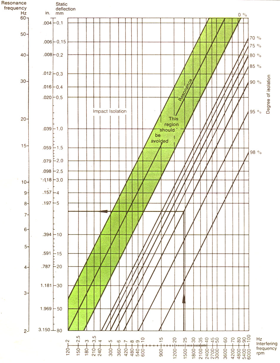
Determine the disturbing frequencies which are usually primary and/or secondary orders of the slowest speed of the machine.
Decide on the minimum amount of isolation required. Normally aim for more than 80%.
With reference to the basic vibration chart, assess the deflection required on the mounts which when under load will operate at the desired natural frequency.
Decide on the type and number of mounts required after reference to the static spring rate characteristics which indicate the load/deflection and load capacity details, bearing the following points in mind:
a) All mounts must be equally deflected.
b) It is better if all mounts are equally loaded, and equidistant from the C. G.
Fix the mounting positions around the machine so that each mount will be equally loaded. This is achieved by ensuring that the algebraic sum of the horizontal centre distances of the mountings about the Centre of Gravity equals to zero. This exercise must be carried out in both directions. Long spans between mounting points should be avoided and normally limited to 3 to 4 feet although this figure is obviously dependent upon the structural rigidity of the machine or the sub-base on which the driver and driver units should be fixed.
If it is not possible to distribute the mounts symmetrically about the Centre of Gravity it will be necessary to take moments to assess the load reactions at the most convenient mounting points. This is needed to determine a modified mounting stiffness requirement to give uniform deflections on all mounts.