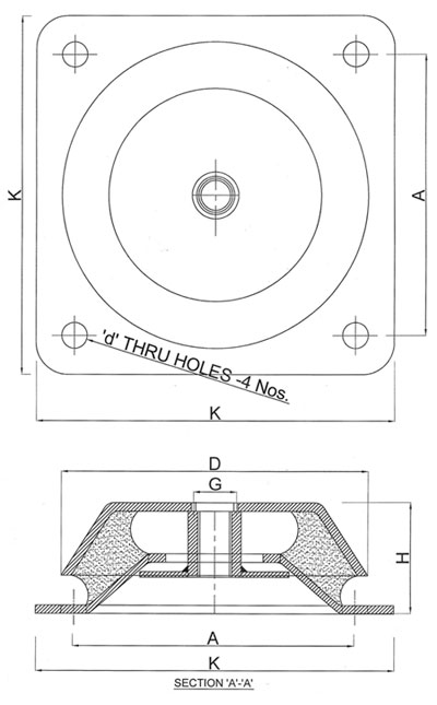
| VIBRO DAMPER | Cup Dia'D'
|
PCD Betw. 2 Holes 'A'
|
Base Length 'K'
|
Height 'H'
|
Dia 4 Holes 'd'
|
Tapping Size 'G'
|
| AVM 600 / 2200 | 144 |
132 |
168 |
52 |
12 |
M16 |
| AVM 1200 / 3000 | 168 |
150 |
184 |
61.5 |
12.5 |
M20 |
* All above mentioned dimensions are in mm
| VIBRO DAMPER | TYPE | MAX. LOAD "Kg." | DEFLECTION "mm." | PAINT / MARKS |
| AVM 600 / 2200 | A |
600 |
5 |
Blue |
| AVM 600 / 2200 | B |
1200 |
5 |
Grey |
| AVM 600 / 2200 | C |
1800 |
5 |
Red |
| AVM 600 / 2200 | D |
2200 |
5 |
Green |
| AVM 1200 / 3000 | A |
1200 |
5 |
Blue |
| AVM 1200 / 3000 | B |
2000 |
5 |
Grey |
| AVM 1200 / 3000 | C |
2600 |
4 |
Red |
| AVM 1200 / 3000 | D |
3000 |
4 |
Green |
Installation of equipments on VIBRO DAMPERS is the modern method of installing equipment which must be protected from shock and vibrations which are inherent in many environments.
In mobile applications the equipments remains steady and isolated from the base vibrations during transit.